
Microservices - Deep Dive

Domain Driven Design Pattern
Domain-Driven Design (DDD) is an approach to software development that focuses on understanding and modeling the problem domain within which a software system operates. DDD provides a set of principles, patterns, and practices to help developers effectively capture and express domain concepts in their software designs.
the design decisions are based on a deep understanding of the domain, rather than being driven solely by technical considerations or implementation details.
“Design” refers to the process of creating a plan or blueprint for the software system.
Ubiquitous Language (Universal Language)
Since non-technical people also work with these models, it is convenient if the models can be represented in different ways. Typically, a model of a domain can be depicted as a UML sketch, as code, and in the language of the domain. In DDD, we use ubiquitous language for describing the model so that non developer can also understand.
Strategic design
Strategic Design in Domain-Driven Design (DDD) focuses on defining the overall architecture and structure of a software system in a way that aligns with the problem domain.
Strategic design is about design in the large, and helps focus on the many parts that make up the large model, and how these parts relate to each other. This helps achieve just a little bit of big design up front, enough to make progress
Bounded Contexts
Context is the problem area which is being solved. For each model, explicitly define the context in which it exists. There are no rules to creating a context, but it is important that everyone understands the boundary conditions of the context.
Contexts can be created from (but not limited to) the following:
· how teams are organized
· the structure and layout of the code base
· usage within a specific part of the domain
Context Maps
Context mapping is a design process where the contact points and translations between bounded contexts are explicitly mapped out. Focus on mapping the existing landscape, and deal with the actual transformations later.


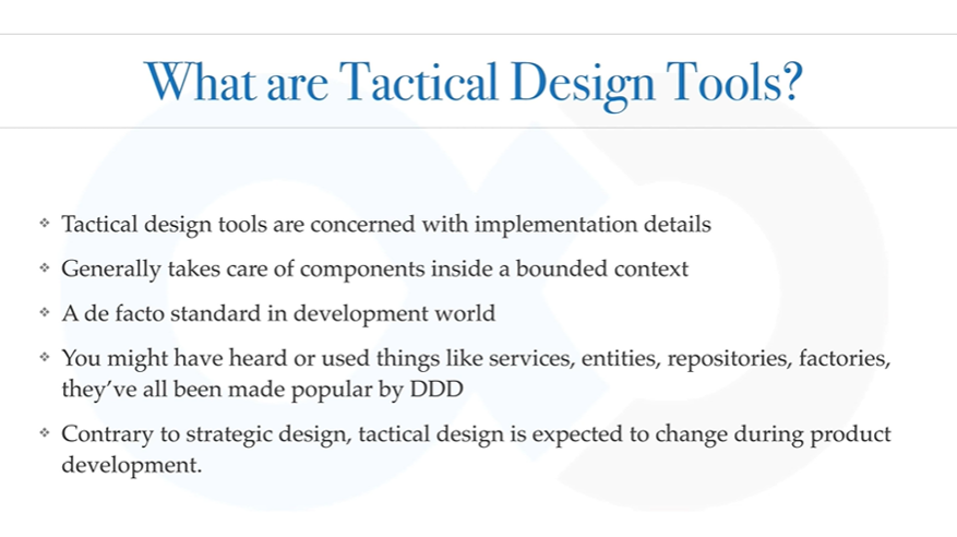

Patterns for Context Mapping
There are several patterns that can be applied during context mapping. Some of these context mapping patterns are explained below.
1) Shared Kernel
This is a bounded context that is a subset of the domain that different teams agree to share. It requires really good communication and collaboration between the teams. Remember that it is not a common library for everything.
2) Customer/Supplier Development Teams
When one bounded context serves or feeds another bounded context, then the downstream context has a dependency on the upstream context. Knowing which context is upstream and downstream makes the role of supplier (upstream) and customer (downstream) explicit. The two teams should jointly develop the acceptance tests for the interfaces and add these tests to the upstream bounded context's continuous integration. This will give customer team confidence to continue development without fear of incompatibility.
3) Conformist (to act according to or be obedient to a rule or norm)
When the team working with the downstream context has no influence or opportunity to collaborate with the team working on the upstream context, then there is little option but to conform to the upstream context.
4) Anti-corruption Layer
When contexts exist in different systems and attempts to establish a relationship result in the 'bleeding' of one model into the other model, then the intention of both will be lost in the mangled combination of the models from the two contexts. In this case, it is better to keep the two contexts well apart and introduce an isolating layer in-between that is responsible for translating in both directions. This anti-corruption layer allows clients to work in terms of their own models.
For example, when a legacy application is migrated to a modern system, it may still need existing legacy resources. New features must be able to call the legacy system. This is especially true of gradual migrations, where different features of a larger application are moved to a modern system over time.
When to use this pattern:
· A migration is planned to happen over multiple stages, but integration between new and legacy systems needs to be maintained.
· Two or more subsystems have different semantics, but still need to communicate.
5) Separate Ways
Critically analyze the mappings between bounded contexts. If there are no indispensable functional relationships, then keep the context separate. The rationale is that integration is costly and can yield very low returns.
Different Definition
Subdomains and bounded contexts are concepts that sometimes appear to be similar and can be confusing. However, both concepts can be easily understood by looking at the difference between a domain and domain model, which is probably easier to grasp. The domain represents the problem to solve; the domain model is the model that implements the solution to the problem. Likewise, a subdomain is a segment of the domain, and a bounded context is a segment of the solution.
Design Patterns for Micro services

Microservice architecture has become the de facto choice for modern application development. Though it solves certain problems, it is not a silver bullet. It has several drawbacks and when using this architecture, there are numerous issues that must be addressed. This brings about the need to learn common patterns in these problems and solve them with reusable solutions. Thus, design patterns for microservices need to be discussed. Before we dive into the design patterns, we need to understand on what principles microservice architecture has been built:
Resiliency
Availability
Scalability
Independent, autonomous
Decentralized governance
Continuous delivery through DevOps
Auto-Provisioning
Failure isolation
(RASID CAF)
Modernization typically involves two types of projects:
• Brownfield projects involve developing and deploying a new software system within the context of existing or legacy systems.
• Greenfield projects involve creating a system from scratch for a completely new environment, without any legacy code involved.
Patterns for decomposing monoliths
Applying all these principles brings several challenges and issues. Let's discuss those problems and their solutions.
1. Decomposition Patterns
a. Decompose by Business Capability
You can use your organization's business process or capabilities to decompose a monolith. A
business capability is what a business does to generate value (for example, sales, customer service,
or marketing). Typically, an organization has multiple business capabilities and these vary by sector
or industry. Use this pattern if your team has enough insight into your organization's business units
and you have subject matter experts (SMEs) for each business unit.
Problem
Microservices is all about making services loosely coupled, applying the single responsibility principle. However, breaking an application into smaller pieces has to be done logically. How do we decompose an application into small services?
Solution
One strategy is to decompose by business capability. A business capability is something that a business does in order to generate value. The set of capabilities for a given business depend on the type of business. For example, the capabilities of an insurance company typically include sales, marketing, underwriting, claims processing, billing, compliance, etc. Each business capability can be thought of as a service, except its business-oriented rather than technical.
b. Decompose by Subdomain
This pattern uses a domain-driven design (DDD) subdomain to decompose monoliths. This approach breaks down the organization’s domain model into separate subdomains that are labeled as core (a key differentiator for the business), supporting (possibly related to business but not a Decompose by subdomain 6 AWS Prescriptive Guidance Decomposing monoliths into microservices differentiator), or generic (not business-specific). This pattern is appropriate for existing monolithic systems that have well-defined boundaries between subdomain-related modules.
Problem
Decomposing an application using business capabilities might be a good start, but you will come across so-called "God Classes" which will not be easy to decompose. These classes will be common among multiple services. For example, the Order class will be used in Order Management, Order Taking, Order Delivery, etc. How do we decompose them?
Solution
For the "God Classes" issue, DDD (Domain-Driven Design) comes to the rescue. It uses subdomains and bounded context concepts to solve this problem. DDD breaks the whole domain model created for the enterprise into subdomains. Each subdomain will have a model, and the scope of that model will be called the bounded context. Each microservice will be developed around the bounded context.
Note: Identifying subdomains is not an easy task. It requires an understanding of the business. Like business capabilities, subdomains are identified by analyzing the business and its organizational structure and identifying the different areas of expertise.

c. Strangler Pattern
Problem
So far, the design patterns we talked about were decomposing applications for greenfield, but 80% of the work we do is with brownfield applications, which are big, monolithic applications. Applying all the above design patterns to them will be difficult because breaking them into smaller pieces at the same time it's being used live is a big task.
Solution (strangles means neck)
The Strangler pattern comes to the rescue. The Strangler pattern is based on an analogy to a vine that strangles a tree that it’s wrapped around. This solution works well with web applications, where a call goes back and forth, and for each URI call, a service can be broken into different domains and hosted as separate services. The idea is to do it one domain at a time. This creates two separate applications that live side by side in the same URI space. Eventually, the newly refactored application “strangles” or replaces the original application until finally you can shut off the monolithic application.
Advantages
· It allows for incremental migration to a new system.
· It allows to pause and even stop the migration while still taking advantage of the new system built so far.
· Each step is reversible, reducing the risk of each incremental step.
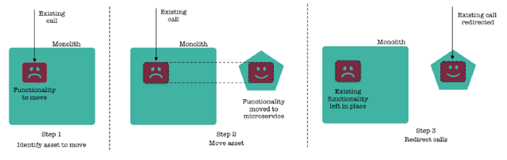
There are 3 stages in strangler pattern - Transform, Co-exist and Eliminate.
1. Transform
2. Co-exist
3. Eliminate
d. Bulkhead Pattern
Isolate elements of an application into pools so that if one fails, the others will continue to function. This pattern is named Bulkhead because it resembles the sectioned partitions of a ship’s hull. Partition service instances into different groups, based on consumer load and availability requirements. This design helps to isolate failures, and allows you to sustain service functionality for some consumers, even during a failure.
e. Sidecar Pattern
Sidecar by name is assisting entity that stays attached with main application and perform some action to extend or improve the parent container like as sidecar of motorbikes. Rather than adding additional logics on main container other than application logics and dependencies, it’s better to employ sidecar container for better performance, enhance functionality and maintainable. It isn’t necessary to use container only as sidecar but in this post, we will focus keeping sidecar container in center.
XRE Project custom appenders.

Example:
(a) Sending logs of application to logging servers: There are numerous logging service providers paid and open source.
(b) Git sync: This is simple way of updating application code and keep in sync with the respective git repo.
2. Integration Patterns
a. API Gateway Pattern
Problem
When an application is broken down to smaller microservices, there are a few concerns that need to be addressed:
1. How to call multiple microservices abstracting producer information.
2. On different channels (like desktop, mobile, and tablets), apps need different data to respond for the same backend service, as the UI might be different.
3. Different consumers might need a different format of the responses from reusable microservices. Who will do the data transformation or field manipulation?
4. How to handle different type of Protocols some of which might not be supported by producer microservice.
Solution
An API Gateway helps to address many concerns raised by microservice implementation, not limited to the ones above.
1. An API Gateway is the single point of entry for any microservice call.
2. It can work as a proxy service to route a request to the concerned microservice, abstracting the producer details.
3. It can fan out a request to multiple services and aggregate the results to send back to the consumer.
4. One-size-fits-all APIs cannot solve all the consumer's requirements; this solution can create a fine-grained API for each specific type of client.
5. It can also convert the protocol request e.g. AMQP (Advanced Message Queuing Protocol) to another protocol (e.g. HTTP) and vice versa so that the producer and consumer can handle it.
6. It can also offload the authentication/authorization responsibility of the microservice.
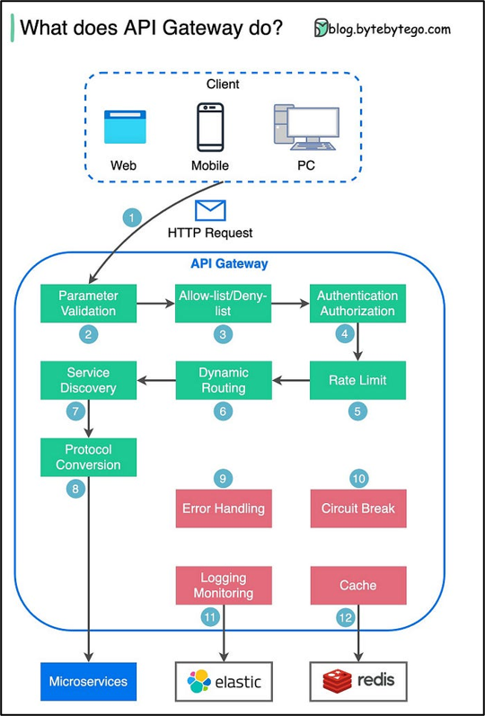
Step 1 — The client sends an HTTP request to the API gateway.
Step 2 — The API gateway parses and validates the attributes in the HTTP request.
Step 3 — The API gateway performs allow-list/deny-list checks.
Step 4 — The API gateway talks to an identity provider for authentication and authorization.
Step 5 — The rate-limiting rules are applied to the request. If it is over the limit, the request is rejected.
Steps 6 and 7 — Now that the request has passed basic checks, the API gateway finds the relevant service to route to by path matching.
Step 8 — The API gateway transforms the request into the appropriate protocol and sends it to backend microservices.
Steps 9–12: The API gateway can handle errors properly, and deals with faults if the error takes a longer time to recover (circuit break).
It can also leverage ELK (Elastic-Logstash-Kibana) stack for logging and monitoring. We sometimes cache data in the API gateway.
Notable API Gateways
Netflix API Gateway: Zuul
Amazon API Gateway
Kong API Gateway
Apigee API Gateway
MuleSoft
What are the differences between a load balancer and an API gateway?
NLB (Network Load Balancer) is usually deployed before the API gateway, handling traffic routing based on IP. It does not parse the HTTP requests.
ALB (Application Load Balancer) routes requests based on HTTP header or URL and thus can provide richer routing rules. We can choose the load balancer based on routing requirements. For simple services with a smaller scale, one load balancer is enough.
The API gateway performs tasks more on the application level. So it has different responsibilities from the load balancer.
The diagram below shows the detail. Often, they are used in combination to provide a scalable and secure architecture for modern web apps.

b. Aggregator Pattern
Problem
We have talked about resolving the aggregating data problem in the API Gateway Pattern. However, we will talk about it here holistically. When breaking the business functionality into several smaller logical pieces of code, it becomes necessary to think about how to collaborate the data returned by each service. This responsibility cannot be left with the consumer, as then it might need to understand the internal implementation of the producer application.
Solution
The Aggregator pattern helps to address this. It talks about how we can aggregate the data from different services and then send the final response to the consumer. This can be done in two ways:
1. A composite microservice will make calls to all the required microservices, consolidate the data, and transform the data before sending back.
2. An API Gateway can also partition the request to multiple microservices and aggregate the data before sending it to the consumer.
It is recommended if any business logic is to be applied, then choose a composite microservice. Otherwise, the API Gateway is the established solution.
c. Client-Side UI Composition Pattern
Problem
When services are developed by decomposing business capabilities/subdomains, the services responsible for user experience have to pull data from several microservices. In the monolithic world, there used to be only one call from the UI to a backend service to retrieve all data and refresh/submit the UI page. However, now it won't be the same. We need to understand how to do it.
Solution
With microservices, the UI has to be designed as a skeleton with multiple sections/regions of the screen/page. Each section will make a call to an individual backend microservice to pull the data. That is called composing UI components specific to service. Frameworks like AngularJS and ReactJS help to do that easily. These screens are known as Single Page Applications (SPA). This enables the app to refresh a particular region of the screen instead of the whole page.
3. Database Patterns
a. Database per Service
Problem
There is a problem of how to define database architecture for microservices. Following are the concerns to be addressed:
1. Services must be loosely coupled. They can be developed, deployed, and scaled independently.
2. Business transactions may enforce invariants that span multiple services.
3. Some business transactions need to query data that is owned by multiple services.
4. Databases must sometimes be replicated and sharded in order to scale.
5. Different services have different data storage requirements.
Solution
To solve the above concerns, one database per microservice must be designed; it must be private to that service only. It should be accessed by the microservice API only. It cannot be accessed by other services directly. For example, for relational databases, we can use private-tables-per-service, schema-per-service, or database-server-per-service. Each microservice should have a separate database id so that separate access can be given to put up a barrier and prevent it from using other service tables.
b. Shared Database per Service
Problem
We have talked about one database per service being ideal for microservices, but that is possible when the application is greenfield and to be developed with DDD. But if the application is a monolith and trying to break into microservices, de-normalization is not that easy. What is the suitable architecture in that case?
Solution
A shared database per service is not ideal, but that is the working solution for the above scenario. Most people consider this an anti-pattern for microservices, but for brownfield applications, this is a good start to break the application into smaller logical pieces. This should not be applied for greenfield applications. In this pattern, one database can be aligned with more than one microservice, but it has to be restricted to 2-3 maximum, otherwise scaling, autonomy, and independence will be challenging to execute.
c. Command Query Responsibility Segregation (CQRS)
Problem
Once we implement database-per-service, there is a requirement to query, which requires joint data from multiple services — it's not possible. Then, how do we implement queries in microservice architecture?
Solution
CQRS suggests splitting the application into two parts — the command side and the query side. The command side handles the Create, Update, and Delete requests. The query side handles the query part by using the materialized views. The event sourcing pattern is generally used along with it to create events for any data change. Materialized views are kept updated by subscribing to the stream of events.
The event sourcing persists an aggregate as a sequence of events and each event represents a state change of the aggregate.
In Event Sourcing, event aggregates are stored as a sequence of events in a database, which is known as an Event Store.
+------------------+
| API Gateway |
+--------+---------+
|
+-----------+-----------+
| |
+--------v--------+ +--------v--------+
| Command Service | | Query Service |
+-----------------+ +-----------------+
| |
| writes to | reads from
+-------v--------+ +--------v--------+
| Event Store |<----->| Read Database |
| / DB + Events | | (optimized read)|
+----------------+ +-----------------+
d. Saga Pattern
Problem
When each service has its own database and a business transaction spans multiple services, how do we ensure data consistency across services? For example, for an e-commerce application where customers have a credit limit, the application must ensure that a new order will not exceed the customer’s credit limit. Since Orders and Customers are in different databases, the application cannot simply use a local ACID transaction.
Solution
A Saga represents a high-level business process that consists of several sub requests, which each update data within a single service. Each request has a compensating request that is executed when the request fails. It can be implemented in two ways:
Choreography — When there is no central coordination, each service produces and listens to another service’s events and decides if an action should be taken or not.
Orchestration — An orchestrator (object) takes responsibility for a saga’s decision making and sequencing business logic.
4. Observability Patterns
a. Log Aggregation
Problem
Consider a use case where an application consists of multiple service instances that are running on multiple machines. Requests often span multiple service instances. Each service instance generates a log file in a standardized format. How can we understand the application behavior through logs for a particular request?
Solution
We need a centralized logging service that aggregates logs from each service instance. Users can search and analyze the logs. They can configure alerts that are triggered when certain messages appear in the logs. For example, PCF does have Log aggeregator, which collects logs from each component (router, controller, diego, etc...) of the PCF platform along with applications. AWS Cloud Watch also does the same.
b. Performance Metrics
Problem
When the service portfolio increases due to microservice architecture, it becomes critical to keep a watch on the transactions so that patterns can be monitored and alerts sent when an issue happens. How should we collect metrics to monitor application performance?
Solution
A metrics service is required to gather statistics about individual operations. It should aggregate the metrics of an application service, which provides reporting and alerting. There are two models for aggregating metrics:
Push — the service pushes metrics to the metrics service e.g. NewRelic, AppDynamics
Pull — the metrics services pulls metrics from the service e.g. Prometheus
c. Distributed Tracing
Problem
In microservice architecture, requests often span multiple services. Each service handles a request by performing one or more operations across multiple services. Then, how do we trace a request end-to-end to troubleshoot the problem?
Solution
We need a service which
Assigns each external request a unique external request id.
Passes the external request id to all services.
Includes the external request id in all log messages.
Records information (e.g. start time, end time) about the requests and operations performed when handling an external request in a centralized service.
Spring Cloud Slueth, along with Zipkin server, is a common implementation.
Spring Cloud Sleuth is a distributed tracing framework that seamlessly integrates with Spring Boot applications to provide insights into the flow of requests across microservices. It generates and propagates unique trace and span IDs, allowing developers to trace requests as they traverse through various components.
@EnableSleuth
By default, Spring Cloud Sleuth will use the LogTraceListener to log trace information. However, you may want to customize the configuration. Ensure that your application.properties or application.yml includes a unique service name to help identify your microservice in traces:
spring.application.name=my-service
Spring Cloud Sleuth automatically instruments common components such as HTTP requests, asynchronous methods, and messaging systems. Spring Cloud Sleuth automatically generates and propagates a correlation ID, allowing you to correlate logs across multiple services. As a result, you’ll start seeing trace information in your logs without any additional code changes.
@Autowired
private Tracer tracer;
Span currentSpan = tracer.currentSpan();
String correlationId = currentSpan.context().traceId();
logger.info("Handling hello request with trace ID: {}", correlationId);
a Tracer bean provided by Spring Cloud Sleuth is used to obtain the current Span
d. Health Check
Problem
When microservice architecture has been implemented, there is a chance that a service might be up but not able to handle transactions. In that case, how do you ensure a request doesn't go to those failed instances? With a load balancing pattern implementation.
Solution
Each service needs to have an endpoint which can be used to check the health of the application, such as /health. This API should o check the status of the host, the connection to other services/infrastructure, and any specific logic.
Spring Boot Actuator does implement a /health endpoint and the implementation can be customized, as well.
5. Cross-Cutting Concern Patterns
a. External Configuration
Problem
A service typically calls other services and databases as well. For each environment like dev, QA, UAT, prod, the endpoint URL or some configuration properties might be different. A change in any of those properties might require a re-build and re-deploy of the service. How do we avoid code modification for configuration changes?
Solution
Externalize all the configuration, including endpoint URLs and credentials. The application should load them either at startup or on the fly.
Spring Cloud config server provides the option to externalize the properties to GitHub and load them as environment properties. These can be accessed by the application on startup or can be refreshed without a server restart.
b. Service Discovery Pattern
Problem
When microservices come into the picture, we need to address a few issues in terms of calling services:
1. With container technology, IP addresses are dynamically allocated to the service instances. Every time the address changes, a consumer service can break and need manual changes.
2. Each service URL has to be remembered by the consumer and become tightly coupled.
So how does the consumer or router know all the available service instances and locations?
Solution
A service registry needs to be created which will keep the metadata of each producer service. A service instance should register to the registry when starting and should de-register when shutting down. The consumer or router should query the registry and find out the location of the service. The registry also needs to do a health check of the producer service to ensure that only working instances of the services are available to be consumed through it. There are two types of service discovery: client-side and server-side. An example of client-side discovery is Netflix Eureka and an example of server-side discovery is AWS ALB.
c. Circuit Breaker Pattern
Problem
A service generally calls other services to retrieve data, and there is the chance that the downstream service may be down. There are two problems with this: first, the request will keep going to the down service, exhausting network resources and slowing performance. Second, the user experience will be bad and unpredictable. How do we avoid cascading service failures and handle failures gracefully?
Solution
The consumer should invoke a remote service via a proxy that behaves in a similar fashion to an electrical circuit breaker. When the number of consecutive failures crosses a threshold, the circuit breaker trips, and for the duration of a timeout period, all attempts to invoke the remote service will fail immediately. After the timeout expires the circuit breaker allows a limited number of test requests to pass through. If those requests succeed, the circuit breaker resumes normal operation. Otherwise, if there is a failure, the timeout period begins again.
Netflix Hystrix is a good implementation of the circuit breaker pattern. It also helps you to define a fallback mechanism which can be used when the circuit breaker trips. That provides a better user experience.
d. Blue-Green Deployment Pattern
Problem
With microservice architecture, one application can have many microservices. If we stop all the services then deploy an enhanced version, the downtime will be huge and can impact the business. Also, the rollback will be a nightmare. How do we avoid or reduce downtime of the services during deployment?
Solution
The blue-green deployment strategy can be implemented to reduce or remove downtime. It achieves this by running two identical production environments, Blue and Green. Let's assume Green is the existing live instance and Blue is the new version of the application. At any time, only one of the environments is live, with the live environment serving all production traffic. All cloud platforms provide options for implementing a blue-green deployment.
There are many other patterns used with microservice architecture, like Sidecar, Chained Microservice, Branch Microservice, Event Sourcing Pattern, Continuous Delivery Patterns, and more. The list keeps growing as we get more experience with microservices. I am stopping now to hear back from you on what microservice patterns you are using.
API Gateway:
Typically, users/clients use a forward proxy, while origin servers use a reverse proxy.
Promote this post
Share & amplify
LinkedIn post generator
Generate a polished, professional LinkedIn post from this article. Edit before posting.
Comments (0)